Please read prior to installation, and have proper equipment and safety precautions in place.
For additional information please visit our website at www.soilretention.com or call 800-346-7995.
Installer Qualifications: An experienced installer, preferably certified by the Interlocking Concrete Pavement Institute (ICPI), and who has successfully completed installations of pavers or other pavement systems on projects of similar or larger scope and magnitude is recommended.
Planning: Final surface elevations and tolerances should be as specified on the project plans. Special consideration should be given to layout, slope, drainage, irrigation type/method, root barriers and edging/confinement.
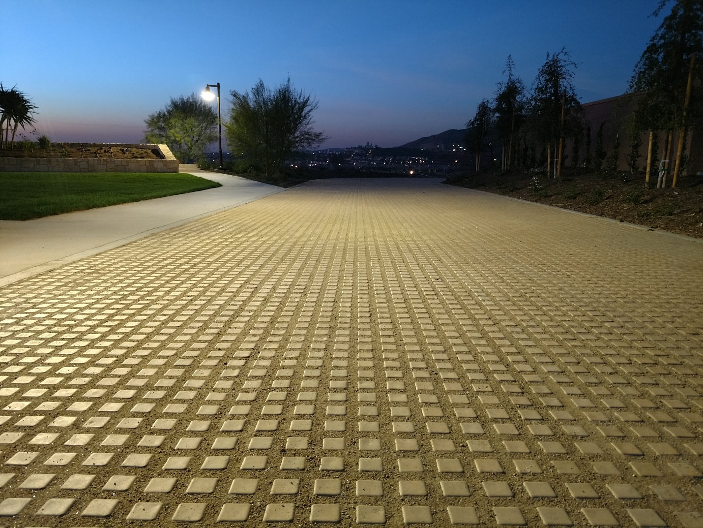
1. Drivable Grass® Material Specification
- Permeable, Flexible, Plantable Pavement System:
- Nominal Dimensions in inches (l x w x h) :
- Gross Area:
- Weight:
- Infill Volume:
- Drivable Grass® mats per pallet (each):
- Area Covered per Pallet:
- Color:
- Flexibility (minimum radius of curvature in inches):
Drivable Grass®
24 in. x 24 in. x 1.5 in.
4 SF
45 lbs.
0.2 CF/Mat or 0.05 CF/SF
60
240 SF
Buff/Tan, Grey
12
2. Main Components of the Installation
- Subgrade Preparation/Subsurface Drainage (if required)
- Perimeter Confinement
- Geotextile Installation (if required)
- Base Material Installation
- Compaction
- Bedding Installation
- Screeding
- Drivable Grass® Mat Placement
- Spike Installation
- Sand Infill for Joints
- Infill
A. Subgrade Preparation
Excavate the installation area to the proper depth to allow for the structural pavement section below the Drivable Grass® installation in accordance with project plans and specifications. Complete any additional over-excavation and re-compaction as required to provide a firm and unyielding subgrade.
Where permeability of the subgrade is important, and site conditions permit excavation into strong native soils, compaction of the subgrade may be minimized to trimming.
Test and approve the subgrade condition and provide written certification confirming the preparation, density and elevations conform to the project plans and specifications. Special consideration should be given for the following conditions:
- Over-excavation depths and re-compaction of subgrade
- Application of filter fabric over prepared subgrade (if required)
- Sub-surface drainage due to low permeable subgrade (if required)
B. Perimeter Confinement
Keeping the edges of the Drivable Grass® installation contained is crucial for a successful long-term installation.
• All driving applications require a concrete mow-strip or existing concrete at edge conditions that will see vehicular access.
• Other edging materials, such as steel or complimenting pavers, can be used in other areas where the edge is not subject to vehicular access. Using pavers as confinement can limit cuts of the Drivable Grass® mats.
C. Geotextile Installation (if required)
Geotextile type should be in accordance with project plans and specifications. At a minimum, the geotextile should be placed at the bottom and sides of the sub-grade and secured in place to prevent wrinkling. Overlap at the seams of the geotextile should be a minimum of 12 inches.
NOTE: Geotextile is always required for clay soils.
D. Base Material Installation
Backfill, level, and compact the required base material to the density, depth/thickness and surface elevation in accordance with the project plans and specifications.
NOTE: A proper aggregate base will contain a gradation of particles that will pack tightly together.
Local, state or provincial standards for aggregate base materials for roads should be used for the gradation and quality of dense-graded aggregate base materials. If no standards exist, follow ASTM D 2940, Standard Specification for Graded Aggregate Material for Bases or Subbases for Highways or Airports. The gradation for base material from this standard is given in the table below. This material should be compacted to a minimum of 95% Standard Proctor density per ASTM D 698 or local standards.
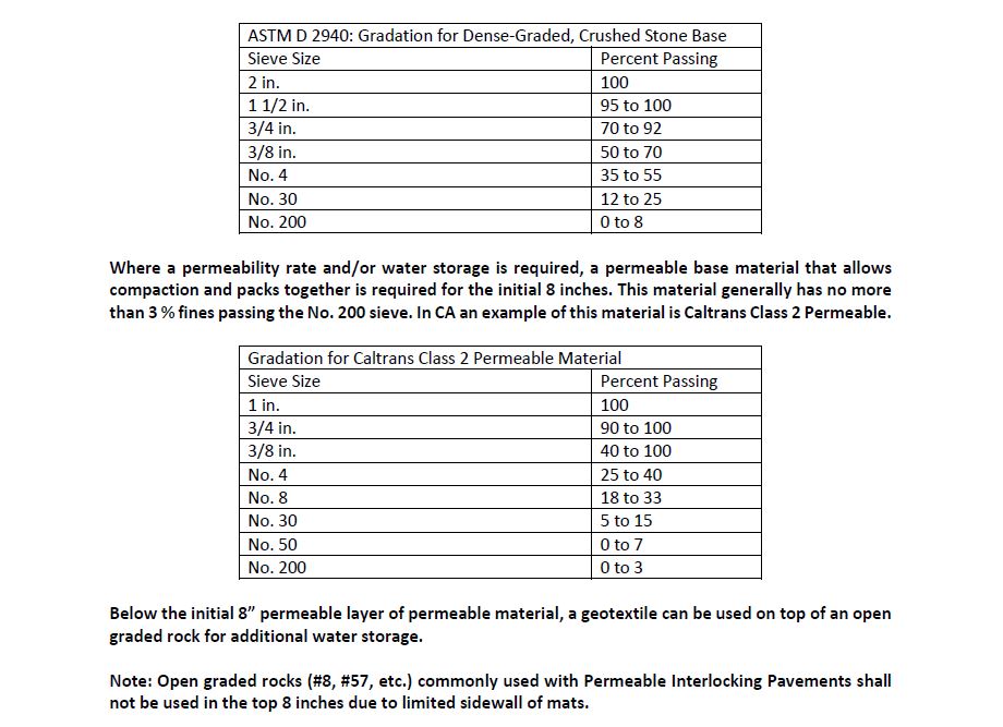
NOTE: Consult with Soil Retention and a local aggregate material supplier where a permeability rate and/or water storage is required. In general, a permeable base material that allows compaction is required for the initial 8 inches. This material generally has no more than 3 % fines passing the No. 200 sieve. In CA an example of this material is Caltrans Class 2 Permeable.
Below the initial aggregate base, a choker course or filter fabric can be used on top of an open graded rock for additional water storage.
E. Compaction Process
To achieve good compaction, use the type of machine that provides the proper force, amplitude, and
frequency. Continue to add and compact base material until the top of the base is approximately 2 in.
below the final height of the finished elevation. The remaining space is for the 0.5 in. of sand bedding and
the 1.5 in.-thick Drivable Grass® mats.
Establish final height by setting string lines to final elevation. The elevation between the material base
and the final elevation should be uniform.
Note: The recommended base surface tolerance should be (+/-) 1/4 in. over a 10 ft. straight edge.
F. Bedding Installation
A minimum uniform bedding thickness of 1/2 inch should be used for non-planted installations.
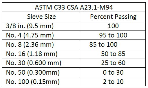
Bedding should consist of clean, non-plastic, sand that is free from deleterious or foreign matter. The sand shall be sharp and manufactured from crushed rock. Do not use limestone screenings or stone dust. The particles shall conform to the grading requirements given in the table below:
NOTE: It is important to moisten, but do not saturate sand bedding prior to installation.
G. Screeding
Spread moist sand uniformly and screed. Use steel pipes, edge restraints and string lines to assure the
screeded sand will allow the top of the and Drivable Grass® mats to conform to designed finished
elevations. Allow 1/8 in. to 1/4 in. above specified surface elevations to compensate for minor settlement.
Note: For Class 2 permeable or equal bases that have voids at the surface, we recommend compacting
the bedding layer to ensure the sand settles into the larger voids at the surface of the base.
H. Drivable Grass® Mat Installation
Install the Drivable Grass® mats in a running bond pattern. Working in one axial direction at a time,
securely butt mats up against each other. Trying to install Drivable Grass® in more than one axis at a
time could result in a significant alignment problem. We recommend a diagonal string line or large 90
degree angle to help with alignment. Make sure to check the alignment in both directions. Make minor
adjustments to Drivable Grass® mats as required to maintain good grid pattern alignment.
Partial mats will be necessary. Fit the area first to avoid ending up with small pieces of the individual pieces
that would likely come lose. Do not drag the Drivable Grass® mats or walk on sand bedding as this can
cause uneven placement.
The grid inside the Drivable Grass® mats can be cut with a utility knife or chisel to fit site conditions. At
terminating edges or curved installations, the mats can also be cut with a masonry blade and using a
powdered chalk line. Be sure to properly clean the Drivable Grass® mats after cutting with a dry blade by
brushing or blowing to avoid staining from fine dust.
Partial mats (minimum of 2 X 2 muffins) should be limited to edges where driving is limited. Make sure to
make minor adjustments to fit large pieces leaving no significant gaps between the edge restraint and the
mats. Secure partial mats using 8 in. spikes in at least two locations. Cut installed full mats as needed
along edges to fit a minimum of 2 X 2 muffins.
1. Seat the Drivable Grass® mats into the bedding course prior to installing any spikes, using a low-amplitude, 75-90 Hz vibrating plate compactor. This will also help get the bedding sand up in the joints between the mats. Use a fabric or pad between the compactor and Drivable Grass® mats to prevent scuffing or chipping.
2. Final surface tolerances should be as follows:
a. Final surface tolerance of Drivable Grass® mats shall not deviate more than (+/-) 1/4 in. over a 10-foot straight edge.
b. Surface elevation of the Drivable Grass® mats shall be 1/8 in. to 1/4 in. above adjacent drainage inlets, concrete collars or other type of inlets.
c. Lippage: No greater than 1/8 in. difference in height between Drivable Grass® mats.
I. Spike Installation (recommended for vehicular driving installations)
Required Tools:
• Air Compressor: 5 CFM at 90 psi (min)
• Air Hose Size: 3/8 in. diameter (min)
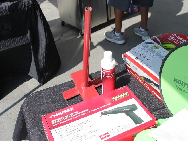
• Soil Retention Installation Kit (see Photo 1)
– Soil Retention Hammer Rod
– Soil Retention Nail Guide
– Air Hammer: 3 CFM at 90 PSI, Stroke length 1.5 in.
– Oil (for Air Hammer)
Note: Frequently check the oil level of the air hammer. Refill oil level as necessary with the oil provided. Operating the air hammer without oil will result in significant damage.
• 8 in. Galvanized Spikes: 2 per mat (spiral spikes recommended for hard / large aggregate penetrations)

Spike Installation Sequence:
a. Place the 8 in. galvanized spikes in two locations (see Photo 2).
b. Using a hammer, set the 8 in. galvanized spikes in place prior to using the air hammer.
c. Place the nail guide over the 8 in. galvanized spike.
d. Using the hammer rod and air hammer, drive the 8 in. spikes to the base of the Drivable Grass® mat (see Photo 3). Do not keep driving the spikes after the end of the hammer rod has reached the base of the nail guide as this may cause damage to the Drivable Grass® mats.
J. Sand Infill for Joints
Note: This step is only required for decorative 3/8” rock. Skip if using decomposed granite or a 3/8” minus rock that contains at least 20% sand.
Required Items and Tools:
• Bedding Sand
• Drop Spreader
• Blower
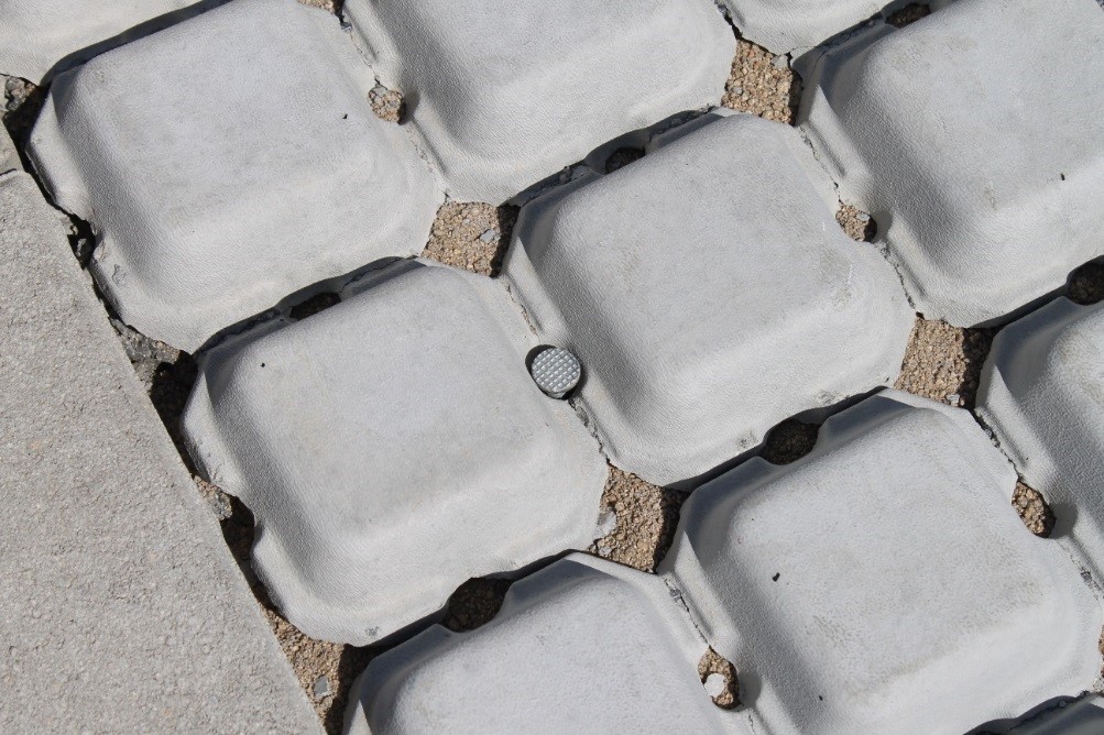
Use a drop spreader and blower, to fill sand to the top of the Drivable Grass® mat base (see Photo 4).
K. Infill
Typical dry infill types:
- Crushed Angular Rock (3/8 minus)
- Decomposed Granite
NOTE: Estimated Infill Volume = 0.2 Cubic Feet per Mat OR 0.05 Cubic Feet per Square Foot
Infill Installation Sequence
a. Spread infill material uniformly across the Drivable Grass® mats with a push broom.
b. The infill should be recessed at least 1/4″ BELOW the mat surface.
c. Lightly water so that infill can self-compact. Re-apply infill as necessary.