


Step 1
Excavate Bottom for First Course
Excavation for bottom course is cut Into a bottom prepared by the grading contractor and accepted by the geotechnical engineer.
Survey stakes for the wall location and heights (TW and BW per structural plan) are set by the civil engineer.
An aggregate base leveling pad can be constructed at this stage if necessary. In most cases leveling pads are not required for Verdura® walls.
Step 2
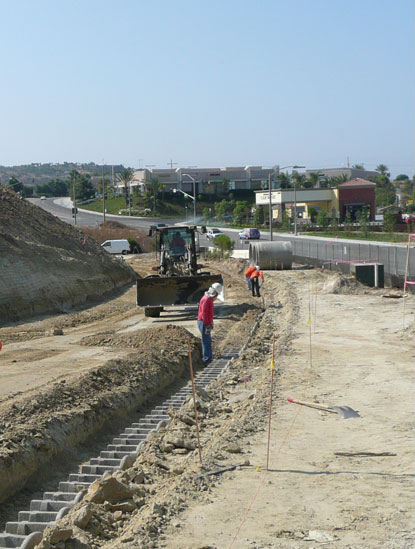
Lay First Course (no footing needed)
First layer of Verdura® blocks are aligned and placed at the bottom of the trench excavation.
Verdura® Retaining Walls can be constructed in a level condition or tilted up to 15% to “run with the grade.”
Concave and convex curves can easily be created with the Verdura® Retaining Wall.
Step 3
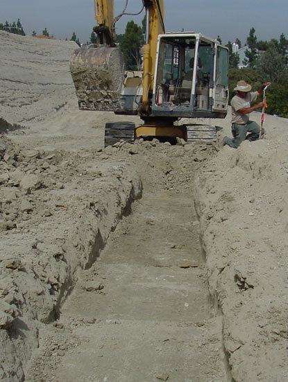
Installation of Subdrain and Outlets
Subdrain is constructed at the rear of the reinforced soil zone.
Typical subdrain consists of a 4-inch perforated PVC pipe encased in ¾” drain rock wrapped in filter fabric (sized as required by the geotechnical engineer).
Outlets for the subdrain are provided through the face of wall or to a specified collection device at intervals recommended by the geotechnical engineer.
Step 4
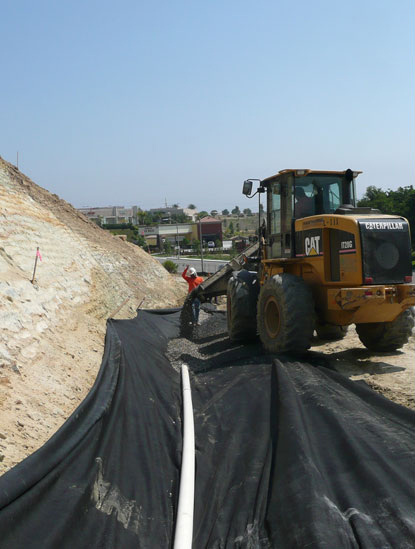
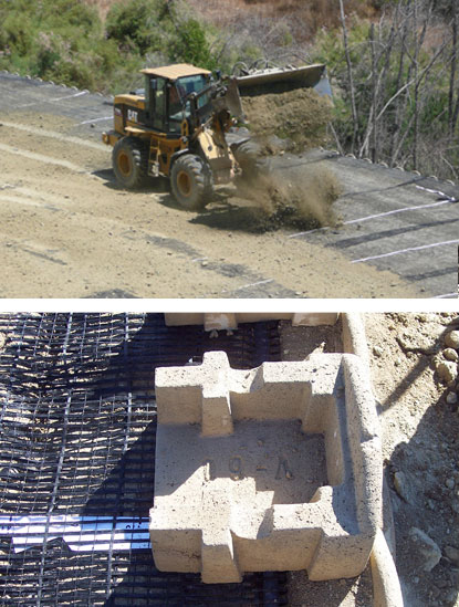
Placement of Backfill Material
Fill material should be approved by geotechnical engineer prior to placement to insure conformance with structural design requirements.
Fill materials for the reinforced zone are placed in the wall for one block level at a time (8” lifts).
The Verdura® system can accommodate loading from heavy construction equipment, and for large walls backfill is typically dumped with scrapers in the grid zone.
Step 5
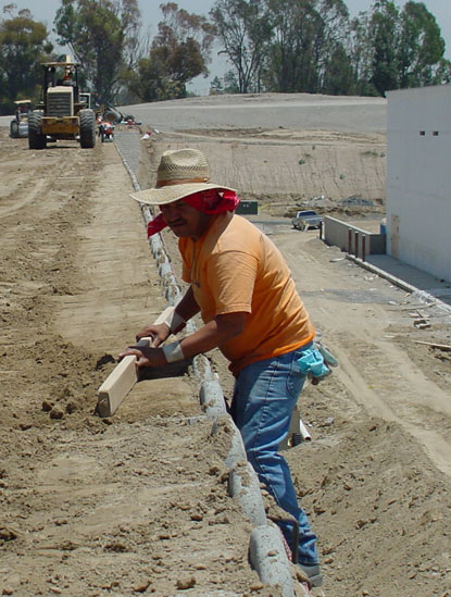
Block Infill and Rod Boarding
Typically, the same backfill material is placed within the blocks as the reinforced zone. In some cases, where required by design, an alternate material is placed in the blocks for planting.
Once the material is placed it is packed in by foot and then rod boarded to create a compacted level area for the next course of blocks.
Note: Since the Verdura® wall is open faced and free draining, an aggregate drainage course behind the blocks is typically not required.
Step 6
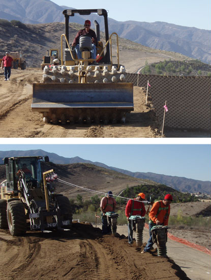
Compaction of Backfill Material
Soils are properly moisturized, mixed, and compacted in single block lifts (typically 6 to 8 Inches).
Compaction testing is to be performed by the geotechnical engineer.
Well compacted soils are key to wall performance!
Step 7
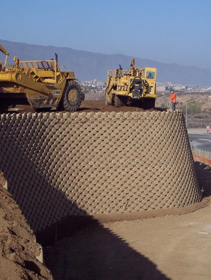
Geogrid Placement & Connection to the Block
The required strength, length, and interval of geogrid is placed per the structural design.
The grid is pulled taut and covered with fill material before scrapers or other large equipment drives on it.
The geogrid is attached to the block with our patented “Positive Connection” … geogrid is wrapped around a Schedule 80 PVC pipe in embedded into a cutout in the block.